
Importance of sheet metal processing technologies in the process of development of feeding systems
Penko MitevORCID ID: 0009-0006-0367-3245Web of Science Researcher ID: MEP-2292-2025Technical University of Sofia, branch Plovdiv, Bulgaria
Kiril MitevTechnical University of Sofia, branch Plovdiv, Bulgaria
https://doi.org/10.53656/adpe-2025.03

Pages 32-39
Abstract. This paper reviews the importance and significance of various sheet metal technologies in the process of development of part feeding systems. Reviewed are the most important types of part feeders, the individual operations that are related to the production of these systems. Main challenges during the design phase are also indicated as well. Focus is spent on the methods and technologies related to the individual operations and a practical experiment is conducted comparing the lead time before and after in-house integration of some of the technologies.
Keywords: part feeding; fiber metal cutting; optimization
- Introduction
The growing demand for high-speed, high-accuracy cutting solutions has driven significant advancements in fiber laser systems, including improvements in beam quality, energy efficiency, and automation capabilities.
A part feeding system is a mechanical or automated system designed to orient, position, and deliver parts in a controlled manner for manufacturing or assembly processes. These systems ensure a continuous and efficient supply of components to machines, robots, or assembly lines, minimizing downtime and improving production efficiency (Boothroyd, 2005).
- Definition of the problem
- Vibratory bowl feeders
- Centrifugal feeders
- Flexible feeders
- Linear feeders
In certain cases flexible feeding systems are preferred in projects where the system has to handle various parts without change-over or with quick change-over within several minutes. Such systems require only software changes (e.g reprogramming of a vision camera) and perhaps changes to the gripping mechanism.
Traditionally part feeding systems remain a strong part of the assembly processes due to the fact that flexible feeders are much more cost-ineffective when there is no part variety. In addition to that, they are much slower and require more maintenance resources.
Bowls mainly made from carbon steel, stainless steel, aluminium and polymers. There are conical, cylindrical, stepped shapes. Most of the technologies require joining of metal parts to form the final bowl assembly. TIG welding is one of the suitable technologies however bowls require parts with complex shape in order to be built. They are designed in 3D CAD software. Then, 2D drawings in DWG/DXF are to be prepared and the part files are loaded onto a fiber laser cutting machines. This is particularly valid for steel bowls. The parts are cut, then a deburring process takes place. Afterwards, welding in TIG is mainly used due to its precision. Nowadays, laser welding is also applied in many cases since it produces great welds and is much easier compared to TIG welding. Even inexperienced users are able to become proficient at it with certain practice.
The main challenges during bowl design are:
- Decrease of design time;
- Optimal design of the bowl and its pathways for smooth part movement;
- Avoidance of hard-to-weld elements – combination of thick and thin steel plates;
- Simulation during design
- Methods and technologies
In Fig.1 are shown the most important operations in the flow of production of bowl feeders. Their significance is shown in absolute value 0-100%.
CAD Design is indicated as 100% since nowadays part geometries are very complex and the use of CAD systems is totally inevitable. Moreover, if a dynamic simulation is to be performed despite the aforementioned limitations, this would only be possible with the presence of a CAD model.
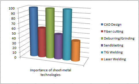
Figure 1. Importance of various technologiesFiber laser cutting is indicated as 60%. On the one hand, this technology is quite popular and has existed on the market for many years. Though it has evolved, the process is relatively clear, there is constant quality among different suppliers and it is reliable. A decisive factor is the existence of the technology at the producing company for bowl feeders. In this case the productivity is rised several times.
Deburring/Grinding is a relatively simple operation and requires some manual processing machines which are commercially available. The factor value however is selected as 100 because this operation takes usually several minutes. In case it is not available in-house this would mean more time resources will be spent on transportation than the work itself. Therefore, conditions for processing it in the company are mandatory.
TIG Welding is also selected as 100 since bowl feeders are devices with high level of know-how and applies technologies. It is seldom that a company would outsource these services to another company under the fear of know-how leaking.
Laser welding is a relatively new technology and is not so widespread for mass production of bowl feeders. Its importance is evaluated as 40% since bowl feeders has been built without it in the past. However, this technology may increase
Sandblasting is one of the most widespread technologies for final finish treatment of parts. When a bowl is ready, it could be sent to a special company so the importance factor is evaluated as 40% as well.
- Productivity evaluation and practical experiments

(1)
Where: TLT – total lead time.
Equation (1) shows that the total lead time is equal to the sum of the individual operations’ lead times for each operation. Fiber laser cutting in the results in Table 1 is shown in two stages since it is observed that normally the the process of building bowls requires two phases of fiber laser cutting as some modifications are required to the main bowl assembly (Dichev et al., 2014).
The data in Table 1 is presented also graphically in Fig. 2. As it could be determined from both the table and the diagram, the time required to produce the bowl is reduced from 185 hours to 52 hours or from approximately 23 days to 6,5 days.
Table 1. Results before and after integration of technologies in-house
| Operation | Required time, [h] | |
| Before integration | After integration | |
| CAD Design | 40 | 40 |
| Fiber cutting 1 stage | 56 | 1 |
| Deburring/Grinding | 1 | 1 |
| Fiber cutting 2 stages | 56 | 1 |
| Sandblasting | 24 | 1 |
| TIG Welding | 8 | 8 |
| Laser Welding | 0 | 0 |
| TOTAL | 185 | 52 |
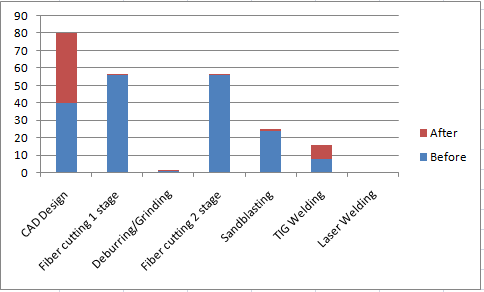
Figure 2. Productivity comparison before and after integration of new technologiesFigure 3 shows the part nesting process as parts are prepared to be cut for the purpose of building series of identical linear feeders. The control software of the fiber laser is Cypcut and it is also used for nesting. Although automatic nesting software capabilities exist, sometimes it is necessary to perform manual movements and adaptations to the position for certain parts.
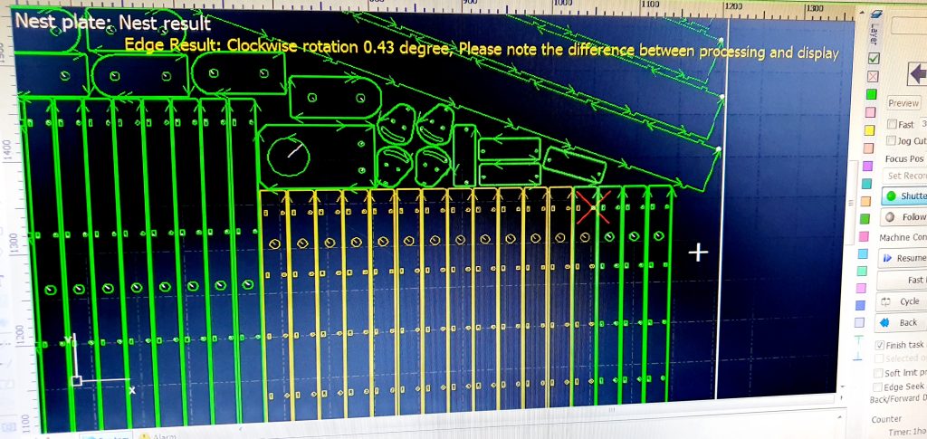
Figure 3. Part nestingAfter nesting and if the other preconditions are met, the machine is ready to cut the parts.
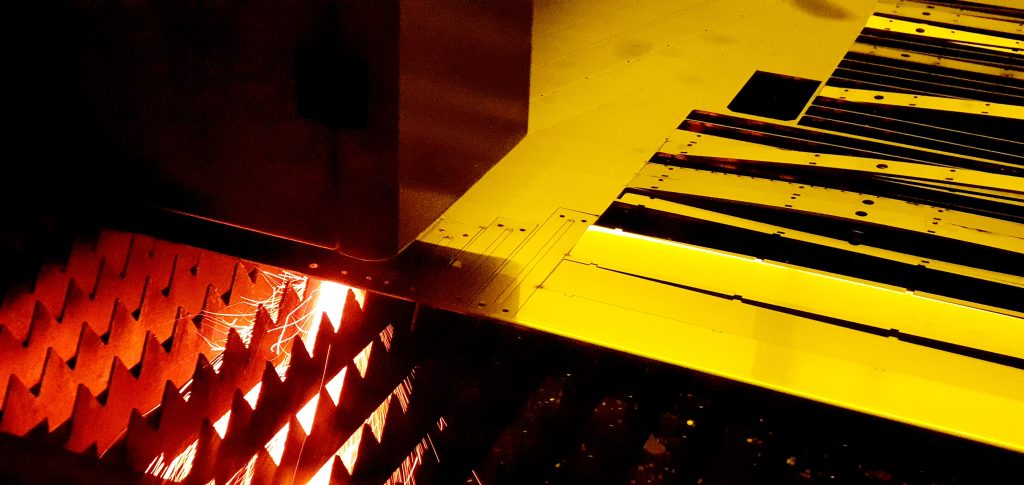
Figure 4. Fiber laser cuttingFigure 4 shows the actual process of fiber cutting. In this specific experiment, the cutting is conducted with stainless steel AISI 304 (1.4301). Practically, each material requires certain cutting parameters to be selected/optimized for sufficient results. Depending on the thickness of the sheet-metal parts, the cutting nozzle is replaced by the operator.
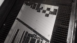
Figure 5. Ready parts after fiber laser cuttingThe parts in Fig. 5 are ready for extraction (sometimes a manual process) and next takes place the deburring/grinding process to remove the small remainings from the fiber cutting process.
- Conclusion
Further optimization to series cutting is possible due to the presence of two tables on this fiber cutting machine. While cutting on the one table, the other is free to be loaded by means of a robot or vacuum-powered sheet transportation tool (Malakov et al., 2023).
Acknowledgement
This research was funded by the Research and Development Sector at the Technical University of Sofia. The authors thank the Research and Development Sector at the Technical University of Sofia for their financial support.
REFERENCES
Boothroyd, G. (2005). Assembly automation and product design. CRC Press.
Chakarski, D., Andonova-Vakarelska T., Sarandeva A. (2000). Methodology for design of robotized technological modules for small parts Proceedings of the NTC for Machine-Building, Sozopol, Bulgaria, 27. [in Bulgarian].
Dichev, D., Koev, H., Bakalova, T., Louda, P. (2014). A gyro-free system for measuring the parameters of moving objects. Measurement Science Review, 14(5), 263 – 269. https://doi.org/10.2478/msr-2014-0036.
Malakov, I., Zaharinov V., Nikolov S., Dimitrova R. (2023). Computer-aided choosing of an optimal structural variant of a robot for extracting castings from die casting machines. Actuators, 12(9), 363. https://doi.org/10.3390/act12090363.