
Designing robotic cells in the environment ROBOGUIDE
Stiliyan NikolovORCID iD: 0000-0002-2485-3847Web of Science Researcher ID: ACY-7901-2022Technical University of Sofia, Bulgaria
Boryan VladimirovTechnical University of Sofia, Bulgaria
https://doi.org/10.53656/adpe-2025.06

Pages 65-73
Abstract. Robotic cells are production cells specialized in the processing of a specific group of products. With the introduction of CARC systems into engineering practice, it became possible to use these systems not only for programming industrial robots, but also in the design of robotic production cells. The article examines the capabilities of the CARC system ROBOGUIDE for designing variants for robotic cells for performing “Pick and Place” operations. The main steps for evaluating the generated variants and selecting the optimal one are defined. Example of using the defined steps is given.
Keywords: CARC system; ROBOGUIDE; FANUC; robotic cells; “Pick and Place”
- Introduction
Despite the wide variety of technological operations performed by robotic cells, the main stages in their design are (Vassilev & Komarski, 2024; Malakov & Zaharinov, 2021; Coletta & Chauhan 2022):
- Assessment of the objects according possibility for robotic production.
- Selection of components and configurations of the robotic cell.
- Modeling, research and determination of cell's characteristics.
- Synchronization of the operation of cell components.
- Development of design documentation.
- Manufacturing, assembly, programming and adjustment of the cell.
- Conducting functional tests and implementation in practice.
This paper examines the possibilities that CARC systems provide to users for developing robotic cells. An example of using the ROBOGUIDE system from FANUC to perform “Pick and Place” operations is given.
- Task statement
- Selection of components and configurations of the robotic cell.
- Modeling, research and determination of cell's characteristics.
- Synchronization of the operation of cell components.
- Manufacturing, assembly, programming and adjustment of the cell.
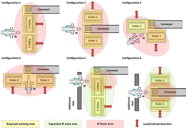
Figure 1. Cell's configurationsFigure 1 shows six possible configurations of the designed cell, taking into account the dimensions of the working area of the industrial robot used. The cell includes the following main components:
- Conveyor – delivers the cartons to the robotic palletizing cell.
- Industrial robot – arranges the cartons on the pallets.
- Pallets – define the area for arranging the cartons.
- Additional axis – provides an expansion of the working area of the industrial robot.
- The industrial robot takes the cartons arriving on the conveyor and stacks them on Pallet 1.
- After Pallet 1 is filled (4 by 4 cartons in a row, with 4 stacking rows), the stacking of the cartons on Pallet 2 begins.
- While the industrial robot stacks the cartons on Pallet 2, Pallet 1 with the cartons stacked on it is taken out of the cell and an empty one is placed in its position.
- After Pallet 2 is filled (4 by 4 cartons in a single level, with 4 stacking levels), the stacking of the cartons on Pallet 1 begins.
- While the industrial robot stacks the cartons on Pallet 1, Pallet 2 with the cartons stacked on it is taken out of the cell and an empty one is placed in its position.
- Steps (2) to (5) are repeated until cartons arrive on the conveyor.
- The position of the conveyor cannot be changed.
- The direction of removal of the pallets from the cage can be parallel or perpendicular to the conveyor.
- Productivity;
- Area occupied.
- Price.
- 3. Design of a robotic cell to perform “Pick and Place” operations in the ROBOGUIDE environment
- Choosing an industrial robot
- End effector selection
- Component Selection
The result of performing these steps when developing configuration 1 from Fig.1 using ROBOGUIDE, for the designed robotic cell is shown in Fig. 2.
A Fanuc R-2000iC/165F robot with a load capacity of 165 [kg] and a reach of 2655 [mm] was selected to perform the operation.
A vacuum gripper is used to manipulate the cartons.
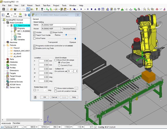
Figure 2. Configuration 1 of the designed cellThe result of performing these steps when developing configuration 5 from Fig.1 using ROBOGUIDE, for the designed robotic cell is shown in Fig. 3.
A Fanuc M10iD/8L robot with a load capacity of 8 [kg] and a reach of 2023 [mm] was selected to perform the operation. An additional linear axis IP-150-RA from IPR Robotics with a length of 3 [m] was used to expand the robot's working area.
A vacuum gripper was used to manipulate the cartons.
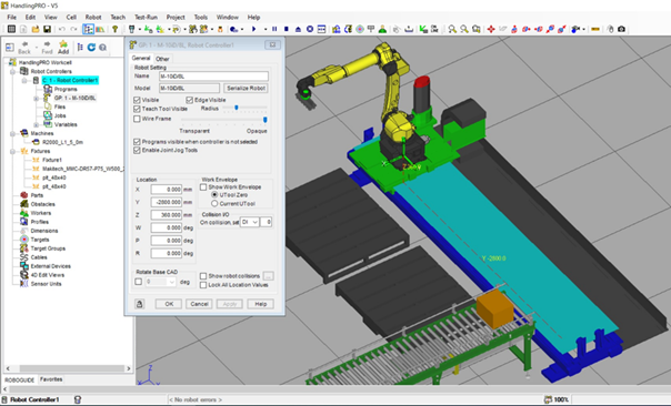
Figure 3. Configuration 5 of the designed cellSteps (1) to (3) are repeated until all configurations for the designed robotic cell are developed.
The positioning of the components is done relative to the robot's Reference Frame or World Reference Frame, as it will be used when programming the robot.
- Analysis of the developed configurations
The result of performing this step for the configurations in Fig.1 using ROBOGUIDE, for the designed robotic cell is shown in Fig.4.
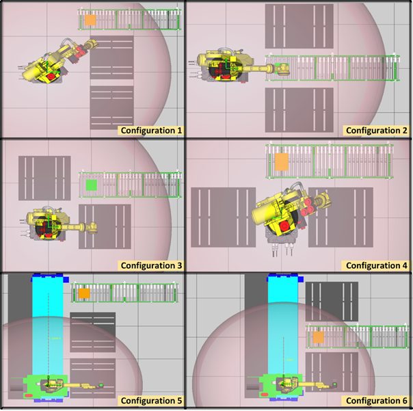
Figure 4. Analysis of the developed configurations in the ROBOGUIDE environmentThe result of the analysis shows that the maximum dimensions of the work areas of the robots selected in step (3) allow the performance of the necessary operations.
- Selection of the cell's configuration
During simulation of operation of cell configuration 4, an incompatibility of the robot's working area with one of the cartons stacking positions is detected.
To solve the problem, it is necessary to change the positions of the pallets relative to the robot, which leads to an increase in the area of the cage and the time for stacking the cartons Fig.5.
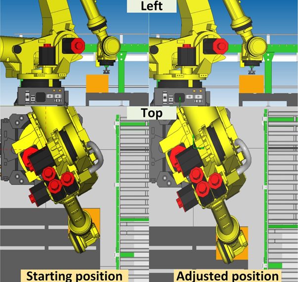
Figure 5. Result of analysis of cell's configuration 4The determined characteristics of the configurations from Fig.1 using ROBOGUIDE, according to the criteria given in the assignment, for the designed robotic cell are given in Table I.
Table 1. Characteristics of the configurations
| Configuration | Time to stack the cartons [min] | Total area [m2] | Price | ||
| Pallet 1 | Pallet 2 | Total | |||
| 1 | 7.58 | 10.91 | 18.49 | 7 | 1 |
| 2 | 7.58 | 7.58 | 15.16 | 8 | 1 |
| 3 | 7.58 | 7.48 | 15.06 | 6 | 0,92 |
| 4 | 10.78 | 10.78 | 21.56 | 9 | 0,93 |
| 5 | 4.86 | 6.20 | 11.06 | 11 | 0,77 |
| 6 | 4.86 | 4.86 | 9.72 | 11 | 0,77 |
The data in Table I show that according to the accepted criteria:
- with the shortest time for arranging the boxes on the two pallets (the highest productivity is configuration 6 - 9.72 [min];
- with the smallest area occupied is configuration 1 7 [m2];
- with the lowest price are configurations 5 and 6.
- Conclusions
These steps are applied in designing a robotic cell for palletizing in the ROBOGUIDE environment. As a result, six configurations of the designed cell were developed. Using ROBOGUIDE, characteristics were determined and used to evaluate the configurations. Based on the evaluation, an optimal variant of the designed cell was selected, according to the criteria of the assignment.
The results obtained show that modern CARC systems are a powerful tool not only for programming industrial robots, but also for designing robotic cells.
The steps defined in this work are universal and can be used when working with different CARC systems.
Acknowledgement
This research was funded by the Research and Development Sector at the Technical University of Sofia. The authors thank the Research and Development Sector at the Technical University of Sofia for their financial support.
REFERENCES
Bulej, V., Bartoš, M., Tlach, V., Bohušík, M., Wiecek, D. (2021). Simulation of manipulation task using iRVision aided robot control in Fanuc RoboGuide software. IOP Conference Series: Materials Science and Engineering, 1199. https://doi.org/10.1088/1757-899X/1199/1/012091.
Biliderov, S., Kambushev, M., Kambushev, K., Marinov, A., Dimitrova, R. (2020). Recovery of GPS Disability to Unmanned Aircrafts by System Modeling. 29th International Scientific Conference Electronics (ET). https://doi.org/10.1109/ET50336.2020.9238254.
Coletta, J., Chauhan, V. (2022). Teaching Industrial Robot Programming using FANUC ROBOGUIDE and iRVision Software. Proceedings of the 16th International Multi-Conference on Society, Cybernetics and Informatics (IMSCI 2022), 45 – 50. https://doi.org/10.54808/IMSCI2022.01.45.
Dimitrova, R., Zhmud, V., Petrov, N., Vakarelska, T. (2019). Study accuracy of a transportation system positioning of a test rig for automated mounting of luster terminals. IOP Conference Series: Materials Science and Engineering, 659, (1). https://doi.org/10.1088/1757-899X/659/1/012031.
Jones, J., G. Leaney, P., Harland, A., Forrester, S. (2012). Validation of RoboGuide to Support the Emulation of Sporting Movements using an Industrial Robot. Procedia Engineering, 34, 307 – 312. https://doi.org/10.1016/j.proeng.2012.04.053.
Marônek, M., Bárta, J., Ertel, J. (2015). Inaccuracies of Industrial Robot Positioning and Methods of Their Correction. Tehnički vjesnik, 22(5), 1207 – 1212. https://doi.org/10.17559/TV-20140416123902.
Malakov, I., Zaharinov, V. (2021). Choosing an Optimal Size Range of the Product “Pipe Clamp”. In R. Matoušek, J. Kudela (Eds), Recent Advances in Soft Computing and Cybernetics (pp. 197-213). https://doi.org/10.1007/978-3-030-61659-5_17.
Mitev, P. (2024). Development of a System for the Active Orientation of Small Screws. Engineering Proceedings, 70(1), 55. https://doi.org/10.3390/engproc2024070055.
Rengevic, A., Kumicakova, D. (2016). New Possibilities of Robot Arm Motion Simulation. Communications - Scientific Letters of the University of Zilina, 18(11), 81 – 86. https://doi.org/10.26552/com.C.2016.1A.81-86.
Vassilev, V., Komarski, D. (2024). Retrofit of a roundness measuring instrument. 34th International Scientific Symposium Metrology and Metrology Assurance, 1 – 5. https://doi.org/10.1109/MMA62616.2024.10817687.